| 3D Elastoplastic Geotechnical Analysis FEM Program |
Let us introduce "GeoFEAS 3D", 3D Elastoplastic Geotechnical Analysis Program, which is currently under development. "GeoFEAS 2D" is usually being utilized for 2 dimensional problems (including axial symmetry) but GeoFEAS 3D has applications dealing with 3 dimensional problems.
GeoFEAS stands for "Geotechnical Finite element Elastoplastic Analysis Software", and it can analyze ground deformation stresses under static conditions. This general-purpose FEM product comes into play when elastoplastic analysis is conducted in various ground-related fields, such as pile foundation analysis, sheathing excavation analysis, shield tunnel cases and slope stability analysis.
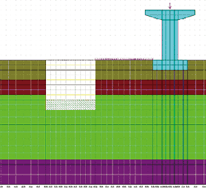
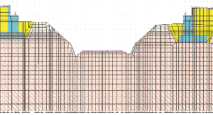
This has been frequently used for in the construction arena, such as the examination of the effects of sheathing work excavation and the subsequent impact on existing piers, as shown in Figure 1(a) as well as the examination of existing railway (screen center) and the effects on the construction of abutment, as shown Figure 2(b). (more information will be explained in paid seminar)
* Figure 1(a), (b) is different from the actual analysis range because only the middle section of the analysis range is taken.
 |
 |
|
Regarding non-linear ground deformation, it is common knowledge to designers that Elastoplastic FEM analysis is integral. Opportunities to conduct FEM analysis are increasing in performance based design in recent years. There appears to be a strong demand due to the current enquiry situation pertaining to the FEM impact analysis of the peripheral ground by "GeoFEAS2D"and "Sheathing work design". Despite our elastoplastic FEM analysis software being 2D, it is in our opinion that pile foundation case, analysis cases of effect on peripheral ground by sheathing work and tunnel excavation, as well as slope stability analysis have to be considered as 3 dimensional problems, for they are originally 3 dimensional terrains. Prof. Ukai, and Assistant professor Fei CAI, Department of Civil & Environmental Engineering, Graduate School of Engineering, Gunma University, who are involved in the development of the solver in our geotechnical analysis series, have strong persuasion in their papers and lectures that 3D analysis is indeed effective and integral.
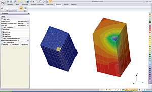
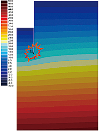
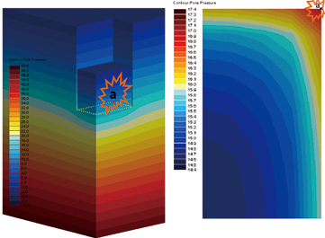
Figure 2 and 3 show the case examples of FEM infiltration flow analysis which were introduced in the special lecture of Prof. Ukai "Current status and problems of geotechnical analysis" being held in Stream-1 geotechnical analysis series/ latest case studies of UC-win/UC-1 User Conference this year. The results of 2D analysis are shown on Figure 2 and the results of 3D analysis are shown on Figure 3. It has been pointed out that local wear & tear are occurring at the corners of retaining wall, despite having a factor of safety of over 1.0 in 2D analysis. Hence, 3D analysis is necessary because solely using 2D analysis is insufficient to produce accurate reflections of the wear and tear.
The examples of infiltration FEM analysis are taken, but 3D analysis in elastoplastic ground analysis is also critical. For example, in large scale projects, it is possible that a 2D based analysis is first conducted. Subsequently, the important concerns are tackled using 3D based analysis.
 |
 |
|
Despite the necessity of 3D analysis being demonstrated and widely introduced, 3D analysis is still not carried out under current circumstances. This might be due to the cost, time, trouble and difficulties of FEM analysis. A simpler tool is required, particularly in areas where model creations involving mesh division and analysis result evaluation depends on a preprocessor (data creating) and a postprocessor (result display). GeoFEAS3D is being developed for product simplification.
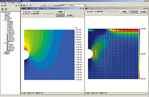
Model creations, mesh divisions, stage settings are carried out in the preprocessor. Sample images of Mesh figure (left) and load condition figures (right) are shown on Figure 4.
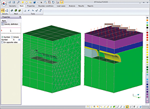 |
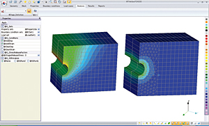
Figure 5 shows the sequential analysis model excavating tunnel from left. When tunnel excavation cases are conducted by 2D analysis, progress of the excavation can be modeled by giving a stress release rate. It can however be seen that excavating conditions has been modeled in the 3D model as shown below.
 |
Pre- post parts of this product are developed by showing our specifications to itech who developed CESAR-LCPC. This means it has the same basic processor as GeoFEAS2D.
Plane elements are used to model the ground in 2D analysis, but solid elements are used in 3D analysis. This product includes tetrahedron, pentahedron, and hexahedron. Plane elements in 2D analysis correspond to plate elements or shell element in 3D analysis, but note that only plate elements are available in the first version of this program.
Defining structure elements (plate elements, beam elements, bar elements, axial direction spring elements, and shear spring elements) allow the expression of interaction of ground with structure and specifying the contact area of joint elements. In addition, deformation analysis and stability analysis of wide problems related to ground like excavation, fill, slope stability, bearing capacity, can be executed by using analysis functions such as stage analysis and shear strength reduction method together.
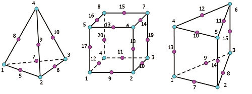 |
Total stress analysis, which doesn't consider percolation of ground water, is available with GeoFEAS, considering water pressure as node load allows the examination of ground effect. Node concentrated nodal load, uniform load, distributed load, volume load (dead load, static earthquake load) are considerable in load.
Single point consonant (a horizontal roller, a plumb roller, anchoring, pin), multi point consonant (MPC, hinge) as well as forced displacement are prepared for boundary conditions.
It corresponds to stage analysis considering construction steps and allowing for the alteration of material constant and boundary conditions by stages.
Although elastoplastic ground analysis is the most basic method under stress examination and ground deformation, many kinds of functions for analysis program are required, because it is important to set analysis model, element definition and application composition model with much care.
GeoFEAS prepares total 15 models from the simplest elastic model to elastoplastic model which can express elastoplastic behaviors of ground for improvement of soil composition models. In addition, No-Tension analysis is available regarding elastic model.
| Model Types | Composition Models | Remarks |
| Elastic models | (1)linear elastic model | isotropy |
| (2)laminated elastic model | orthotropy | |
| Non-linear elastic models | (3)Duncan method 1 | Consider Poisson ratio as constant. |
| (4)Duncan method 2 | Define volume constant | |
| (5)Destruction Approach | CRIEPI Method | |
| Non-linear models | (6)Hrardin-Drnevich model | |
| (7)Ramberg-Osgood model | ||
| (8)Ukai/Wakai model(UW-Clay) | ||
| Elastic perfectly plastic models | (9)Morh-Coulomb Method | associated flow rule/ non-associated flow rule |
| (10)Drucker-Prager Method | associated flow rule/ non-associated flow rule | |
| (11)Morh-Coulomb/Drucker-Prager Method | non-associated flow rule | |
| Elastoplastic models | (12)Pastor-Zienkiewicz sand model | |
| (13)Pastor-Zienkiewicz sand model | ||
| No-Tension models | (14)linear elastic model | |
| (15)laminated elastic model |
