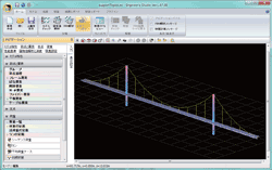
Let's consider the model of the suspension bridge like Figure 1 as an example. This model is a sample "SuspensionBridge.es" attached in Engineer's Studio(R).
The tension shown in Figure 2 is given as an input of the cable element, 100kN is provisionally given before it analyzes it. This 100kN is an initial value of the convergent calculation. When 0kN is given, because the cable element is not approved as an element (It becomes irregular.), some tensions are given as an initial value.
The costraint condition of the node is given in Figure 3. The costraint condition of 0.0mm is given to the row of Δ so as not to displace the node at the floor slab position in a perpendicular direction. Moreover, "Dead-load (St.)" is specified for the load case of the initial state. When the lateral calculation button is pushed, the load case is loaded to the model, the tension of the cable element and the section force of each material are calculated under the condition that the node at the floor slab position is not displaced. Tension of cable element calculated automatically is displayed as an element in the row of TX-i、TY-i、TZ-i、TX-j、TY-j、 TZ-j shown in Figure 4. The curve length of the cable element by the tension provisionally given is displayed in the row of "Length", and the curve length of the cable element calculated by an automatic calculation is displayed in the row of "Length of the initial state". A latter tension is an important result.
 |
|
 |
| Figure1 Sample model of the suspension bridge |
|
Figure2 Tension provisionally
given to cable element |
 |
|
 |
| Figure3 Input the constraint condition of node |
|
Figure4 Tension component of the cable
element calculated automatically |
|

