New Products
UC-win/Road Ver.7
3D real-time VR software

Price: Ultimate  : US$15,750(New) / US$1,575(Version Up)
Driving Sim :US$12,600(New) / US$1,575(Version Up)
Advanced  : US$9,450(New) / US$840(Version Up)
Standard  : US$6,090(New) / US$840(Version Up)
Released: March, 2012
UC-win
simulation
 UC-win/Road・VR seminar
●Date/ Venue : Jun 6, 2012 Sendai 
Jun 8, 2012 Fukuoka
●Time : 9:30-17:35 (VR Engineer exam is conducted.)
●Participation Fee: 15,000yen/ person (tax excluded)
 UC-win/Road Advanced・VR seminar
●Date/ Venue : Jun 20, 2012 Osaka
●Time : 9:30-17:35 (VR Master exam is conducted.)
●Participation Fee: 15,000yen/ person (tax excluded)
 Road Design by VR seminar
●Date/ Venue : April 6, 2012
●Time : 9:30-17:30
●Participation Fee: 15,000yen/ person (tax excluded)
●Venue:Fukuoka branch office
 UC-win/Road Expert/ Training seminar
●Date : April 12-13, 2012
●Time : 12th 13:00-17:30 , 13th 9:30-17:30
     (UC-win/Road Expert exam is conducted.)
●Participation Fee: Free
●Venue:Tokyo head office
UC-win/Road is real-time VR software that can create and use the virtual reality of 3D in an easy PC operation. In Ver.6 released this time, the following functions are added and improved.
 Ver.7 Additional Function
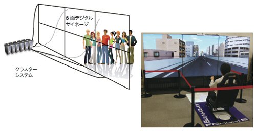
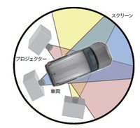
Cluster Function(price on application)
(1)Overview
The cluster system has been developed for use with large-scale and complex driving simulators.
This new system synchronizes the work of two or more PC’s and outputs the resultant image to multiple monitors, thus making it possible to maintain a constantly high level of performance and frame-rate irrespective of the number of channels since each channel is displayed on an independent PC.

It is still possible to output from one PC to two or more monitors without using this cluster option, however you will find the performance of the system decreases as the number of channels increases.

(2)Structure
The cluster system is composed of a master machine and multiple client machines.

Master Machine
The 3D driving simulation is developed and calculated within the user’s master machine.

Client Machine
The client machines receive the information required for displaying the VR space from the master machine.

Channel Synchronization
This system transmits the data from the master machine to the client using multicast on UDP. The number of clients does not depend on the communication performance of the master machine, as by using the multicast software many client machines may be connected, even with standard network hardware.

Synchronization is performed only over an Ethernet network at this time, but in future even better performance will be achieved by use of the Quadro G-Sync system being developed by NVIDIA.

Failsafe Processing
This is a mechanism that ensures that the simulation and synchronization will continue even if an unexpected breakdown occurs in one of the client machines. Moreover, if a client machine fails to respond, the synchronization is automatically restarted.

(3)Channel Composition
This system enables the projection of the VR Space onto a large screen, or an entire sphere, by dividing the image projection between client machines so that each client outputs a certain part of the total image for example the left/right/top image.

Two different settings for the Projection method are available:

  • Large screen composed of two or more monitors or projections for digital signage
  • Projection on to a sphere by plane splitting

Figure1 Digital signage Figure2 Image of dome type
driving simulator

(4)User Interface
The client machines can be easily set up by setting only the master connection information and the client name. The entire simulation operation is controlled from the master machine via an improved user interface. The following functions are available.

At set up: 
  • Confirmation of client machine list and the display settings
  • Server connection information on the master machine, and network settings
During operation:
  • During start or end of synchronization with the clients, or if there is no synchronization, all functions can be used in the same way as the stand-alone version. (When synchronizing, only the simulation function can be used.)
User Interface can be locked within the main screen of UC-win/Road, and can be accessed easily (Figure 5).

画像をクリックすると大きな画像が表示されます。
Figure3 GUI on the master side and driving

(5) License Price
The Cluster System is composed of two components, the master and the client. The master machine requires an additional (separately-priced) cluster option as well as the standard license. Each client machine then requires a ‘viewer licence’ under which the VR data cannot be edited. One client license is required for each channel.

(6)Future Development
  • As for the projection method, the spherical projection will be supported.
  • Supports for edge blending software.
  • As for the synchronization of display frame, G-Sync of NVIDIA will be supported.
  • Several channels will be supported on one client side.

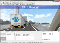
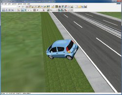
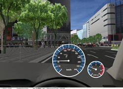
Off Road Function
Users can drive vehicles around the 3D VR space using a steering wheel, a game controller or the keyboard in UC -win/Road.

Previously driving was only possible on a road carriageway; users were not able to drive through the environment if there was no road in the 3D space.

This limitation was removed in UC-win/Road V7. It is now possible to drive off-road and also to start driving anywhere within the environment by setting up a driving start point wherever you wish on the terrain.

画像をクリックすると大きな画像が表示されます。 画像をクリックすると大きな画像が表示されます。
Figure4 Setting the driving start point
Figure5 Scene of vehicle
going off-road

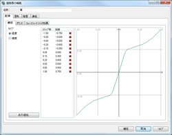
However, the road friction and sound properties must be manually assigned to the terrain when driving off-road. These can be assigned to various terrain textures in the "Edit road surface" window. Other UC-win/Road Drive Simulator features, such as force feedback and scenarios are also available for off-road driving.

画像をクリックすると大きな画像が表示されます。
Figure6 Road friction coefficient can be
assigned in the "Road Surface Editor" window.

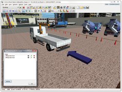
3DS Output Function
This function enables all models within the UC-win/Road 3D space to be output in an arbitrary 3D model data format. This enables users to output data from UC-win/Road in 3DS format for input into such standard CAD tools as 3dStudio Max.
In addition to allowing output in 3DS format, the following output formats will be made available in future: FBX, OBJ, VRML and OpenFlight .

No Output Target
1 Terrain
2 3D model
3 Road
4 Tree(2D)
5 Road attachment (sign, tree, marking etc.)

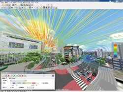
xpswmm plug-in
The script and scenario functions were added to the xpswmm plug-in.
As a result, it is now possible to reproduce a chain of events, such as the height of the water surface, displaying the contours as well as the reflection of a tsunami for example…
The reproduction speed and the repetition or the simulation can be controlled via the playback function.
The display of the analysis results can be controlled according to the simulation and presentation. The analysis data of xpswmm can be utilized more easily and is more interactive than before.

Sidra plug-in
It came to be able to do the import of the design data of latest version (Sidra Intersection 5.1) of intersection design software Sidra by revision of the Sidra plug-in. As a result, importing the shape, the section, the traffic signal control, and the traffic quantity etc. of the intersection designed by latest Sidra will be possible.
  Function under Development
Civil 3D plug-in
The Civil 3D plug-in is a plug-in that achieves an interactive data exchange with three dimensions CAD "Autodesk Civil 3D" for the civil design and construction.
It mainly corresponds to a terrain, road alignment, data exchange of vertical alignment. Older version supported until Civil 3D 2011 conventionally, whereas Ver.7 will support the latest Civil 3D 2012 as well. In addition, not only 32 bit of Civil 3D but also 64 bit will be planned to be supported.

Speedometer
The speedometer and the tachometer can now be displayed during a driving simulation. You can switch this feature ON or OFF within the ‘Visual Display’ options. Moreover, either (km/h) and (MPH) display can be displayed and the display position adjusted.
画像をクリックすると大きな画像が表示されます。
Figure7 Display of speedometer

Support for the video cards manufactured by ATI
Video cards manufactured by NVIDIA have been recommended for use with UC-win/Road, however Forum8 can now support ATI video cards. While most functions operate normally, the following features will not display properly.

1. Road obstacles (textures are broken up)
2. Advanced lighting (Streetlights and headlights cannot be shown.)
3. Sky textures (Not always properly displayed )
4. Shadows

Problems above, 1-3 at least, are planned to be fixed with the release of Ver.7.0,
Moreover 4 will be solved with any one of the minor releases following Ver.7.0.
   Ver.6.1 Additional Function
World file
World file is a file with coordinates information standardized to give coordinates information to the street map (map images of the satellite photograph and the aerial photograph, etc.). By importing the street map together with World file, the street map will be automatically placed on top of the specific geographic location written in the World file. In addition, World file is composed of 6 parameters. The format of World file is shown in the table below.

Line Explanation
1 X scale ( Length(m) of each pixel along the X axis)
2 Rotation angle in X direction
3 Rotation angle in Y direction
4 Minus Y scale ( Length(m) of each pixel along the Y axis)
5 East longitude coordinates on the center of the pixel in the upper left corner of the image file.
6 North latitude coordinates on the center of the pixel in the upper left corner of the image file.

There has been a complete improvement of the street map edit function. As a result, the following adjustments are now possible:

  • Division and movement of images
  • Moving an image to the front or to the back
  • Delete function has been enhanced (you can now delete unused cells at once)

Fluid Analysis Plug-in
This plug-in is used to import a file in VTK format and visualize the stream line in the data used by the VTK format.

The VTK format is a general format, so it's used for various software. However in this plug-in, we assume the fluid analysis result of OpenFOAM is taken in Para View, it's output in VTK format, and visualize and use it by importing it.

*VTK:VTK stands for Visualization Tool Kit and it's an open source library for visualization of 3D computer graphics.
*VTK format:Specified format to make it possible for VTK to exchange data with an external program.

画像をクリックすると大きな画像が表示されます。
Figure8 Visualization of stream line
and setting of color

Munsell Color Space Output Plug-in
Munsell Color Space Output Plug-in is a plug-in which visualizes the spectacle displayed on the main screen of UC-win/Road in "Munsell color system" and saves it as munsell color file. Munsell color system is one of the methods used to represent color by adjusting the numerical value of each of the three attributes color, "Hue, Value and Chroma". Hue means the difference of shade, value means the degree of color brightness and chroma means the vividness of color.

This style of expression is often used in the field of design and art. You can design the spectacle using munsell color or do a research on munsell color by accessing the file that has been output using this plug-in.
Figure9 Output image of munsell color file
  Future Development
In UC-win/Road Ver.8, the advanced visualization of dazzle of light, more realistic expression of the shadow and improvement of reality of driving simulation (expression of the feeling of speed by the motion blur) will be planned to be supported.
(Up&Coming '12  Spring Issue)
Back
Back

FORUM8