New Products
UC-win/Road Ver.6
3D real-time VR software

Price: Ultimate : 1,575,000 Yen(New purchase) / 420,000 Yen (Version up)
Driving Sim : 1,260,000 Yen (New purchase) / 315,000 Yen (Version up)
Advanced : 945,000 Yen (New purchase) / 262,500 Yen (Version up)
Standard : 609,000 Yen (New purchase) / 189,000 Yen (Version up)
Release: November 2011
Simulation

UC-win/RoadVR seminar
Date/Place : November 22, 2011 Fukuoka/Deceme 9 Tokyo
Time: 9:30-17:35 (VR Engineering certified exam)
Participation fee :15,000 Yen /Person (15,750 Yen -Tax inclusive)
UC-win/Road Expert training seminar
Date/Place : November 17-18, 2011
Time : November 17 13:00-17:30
          November 18  9:30-17:30
(UC-win/Road Expert examination)
Participation fee : Free
Location:Tokyo head office seminar room
Design Festival 2011-3Days
November 15, 2011:VRcon.forum8.jp
November 16 and 17: Shinagawa front building
Day2 12th UC-win/Road Conference
(5th International VR Symposium)


UC-win/Road is the real-time 3D Visual Interactive Simulation software that allows the easy creation of immersive 3D virtual reality environments. In Version 6 the following functions are added and improved.

Crowd Movement in 3D
In previous versions the user could only set a predefined walking route (pathway) arranged in 3D space. In this latest version the user can set an area of the 3D environment within which the pedestrians can walk. The result is that the visual reality is improved as well as the time required for arranging multiple numbers of pedestrians (crowd) is greatly reduced.

This new function allows the simulation of the pedestrians to be much nearer to that of actual human behaviour. Moreover, the pedestrians now avoid bumping against each other. Pathways can be connected together to create a network and pedestrians within this network will determine their own routes.

 Figure 1 Movement of walking crowd

(1)What is a Pathway?
The pathway is the same as the "flight path" in the previous versions but with the width added. It consists of a node at the start and end point (blue cubes shown in Figure 2) and the changing point between them (yellow spheres shown in Figure 2), and the inclination of each pathway can be defined by the user.

(2)Dynamic setting of the pathway
Unlike the flight paths, the pathway is directly created in the 3D space of the main screen so that you can easily see the position of the path and adjust the height interactively.

 Figure 2 Pathway

(3)Arranging pedestrian movement
There are two methods for adjusting the movement of the pedestrians. One method generates them automatically at random positions soon after starting the simulation. The other generates them at constant intervals from the specified node. In addition, MD3/FBX pedestrian models which make up the crowd are selected at random from the registered model database.

(4)Walking algorithm
This new function enables individual pedestrians to avoid bumping against each other (Figure 3). The parameters of the walking algorithm include: field of view, view angle, position coordinates and velocity vectors. The pedestrians who are in the 'field of view' per 'time step' are recognized. When other pedestrians are 'seen', they walk by, changing their direction if necessary. In addition, when pedestrians moving in the same direction are detected, the elements relating to these pedestrians are also recognized. This way, the flow of people becomes as smooth as that of a 'real' crowd.

  Figure 3 Pedestrians avoiding collision

(5)Future development
The future development of this Crowd function includes: the integration with traffic, such as waiting at a curb or intersection until traffic lights or pedestrian signals change; a route search to a particular destination and the avoidance of obstacles such as buildings, street furniture and cars.
FBX Model Animation
The import of static 3D models in FBX format was made available in Version 5, but in Version 6, the animation features of the FBX format is made available for import.

(1)FBX animation
The FBX animation supported in Version 6 is called "Bone animation" (Figure 4). Bone (framework) is what controls the 'motion space' of the model in 3D space, with each junction playing the role of a human joint. Therefore the greater the number of bones and thus joints, the greater the motion space and the more complicated and natural the model's motion can be visualised.

All animation calculations are performed by the shader, so the higher volume of models can be simulated at a high frame rate. In addition, the LOD (Level of detail) function ensures maximum performance by reducing the display accuracy of the models that are in the background.

  Figure 4 Example of animation using Bone (Created by using Blender)

(2)Registration of character
FBX models can be used as 'characters' with FBX animation. This registration is performed in the software's "Register character model" tab which is expanded from the existing "Register MD3 character". On this screen, the operations such as: edit, delete, download from the RoadDB and the addition of a mobile object are possible. The edit screen of the FBX scene is open when the edit is selected at which point the execution speed of the animation and scale can be set. (Figure 5).

Figure 5 FBX setting screen

(3)Use with scenario function
FBX model can be used in the scenario function. The registered FBX character model can be selected on the event edit screen of the particular scenario and the edit screen of the target model.
Road DataViewer plug-in
3D model data for such items as objects (buildings, trees etc.,) as well as textures, crosswalks etc. can now be displayed as a list in 'tree' format. The list displayed in the tree format can be locked within the main screen. Also, when the object displayed in the list is selected, the camera will jump to the selected object within the 3D view. Filtering by object names, changing  object names and deleting objects are also possible.

In addition, the following verification functions are available within this plug-in, and the consistency of the data can be verified.
  1. Inspection of the total number of pixels in a texture: search models by maximum and minimum numbers of pixels. 
  2. Inspection of road connection points: search for disconnected roads (e.g. at ramps).
  3. Inspection of buried model: search for models that are buried under the terrain (Figure 6).

 Figure 6 A model buried in the terrain found using the plug-in

IFC plug-in
IFC (Industry Foundation Classes) data model is an international standard level developed by IAI for the purpose of advancing interoperability within the construction industry (the specification of this model is developed and maintained by buildingSMART International).

In this plug-in the terrain data in the file described in IFC format can be imported into Version 6 as a terrain patch. In addition 3D models, such as the terrain or buildings can be exported from VR-Design Studio in IFC format. These IFC files can be imported into other IFC-compatible software (figure 7). The image on the left is the screen from VR-Design Studio (UC-win/Road) and on the right is the screen of an alternative IFC-compatible software.

 Figure 7 UC-win/Road screen and display of IFC format export result

12d Model plug-in
12d Model is an integration solution of terrain modelling, survey and civil design software developed by 12d Solutions in Australia. It's used for a wide range of projects such as road design, construction site layout and environmental impact surveys.

In this new plug-in, "12d Ascii File" formatted data can be imported into Version 6 as shown in Table 1.

Table 1 Bidirectional linkage with 12d Model
UC-win/Road 12d Model
Mesh terrain Tins
Terrain patch Tins
Road alignment String Alignment
12d Model UC-win/Road
Tins Terrain patch
String Alignment Road alignment
String Super Alignment Road alignment
String 4d for road sections Road alignment

When importing 12d Ascii Files into Version 6 the imported terrain (TIN data) and the road alignments are selected along with the 'template' of road cross section information. 'Template' means the data which has the mapping information of the cross-sectional attributes that enable the importing of the 12d model section data, Figure 8.

Moreover, when exporting from Version 6, the objects (terrain, terrain patch, road alignments) are selected and the file name is specified.
 Figure 8 Import result of 12d Ascii File

Linkage with Tsunami Analysis Software
The new xpswmm plug-in is used to visualize the results of the flood analysis from xpswmm.

This Version 6 revision enables the user to show the result of an xpswmm tsunami analysis in a much more realistic manner.

(1)Improvement of Visual Quality
The degree of reflection of at the water surface and the amount of refraction of the light can be adjusted, and the following functions are implemented.
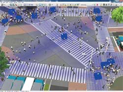
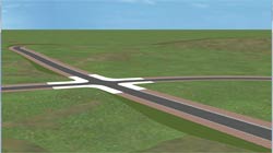
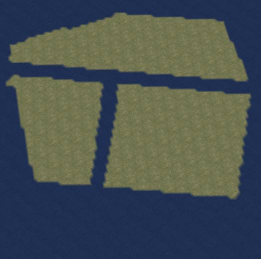
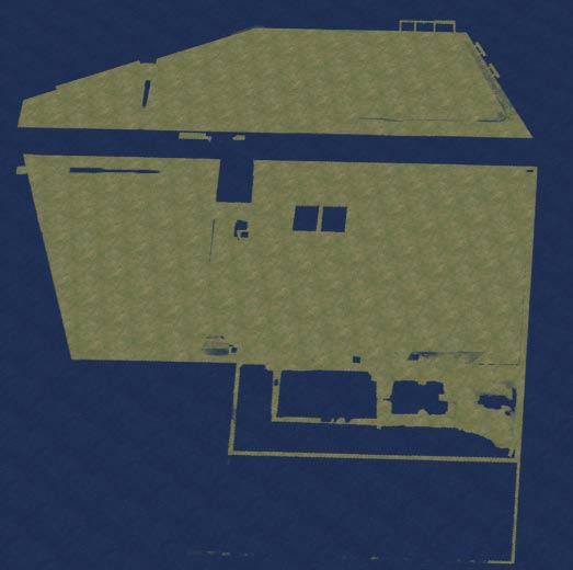
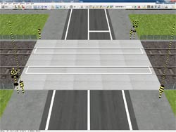
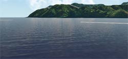
  • Completion of the mesh and the smooth representation of the shoreline (Figure 9)
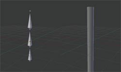
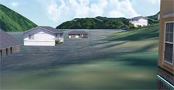
  • Expression of waves on the water surface (Figure 10)
  • Representation of splash 
Figure 9 Smooth shoreline Figure 10 Waves on water

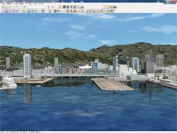
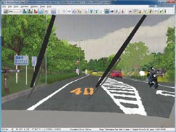
The water surface in Version 6 expresses not only the detailed ripples but the reflection of sky, sun, moon etc., leading to a much more realistic visual representation of the 3D environment.

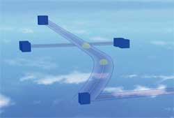
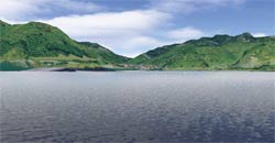
The rate of reflection on the water surface and the light's refraction is calculated using the Fresnel's equation. The image on the left in figure 11, shows a situation that has a great amount of reflection due to the water being shallow, conversely, the 3D water is shown to be much darker in colour if the angle of the visual line is deeper.

Figure 11 More reflection when visual line is shallow (Left)
More refraction when visual line is deep (Right)

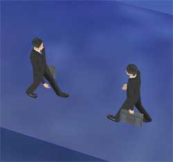
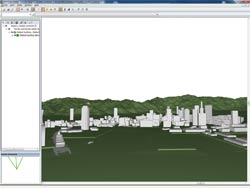
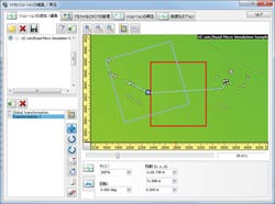
(2)The Visualisation of the Level of Damage to Buildings (Under Development)
In this revision of the software, the drag acting on buildings by the tsunami is calculated and a function that visualizes the degree of building damage is implemented.

The degree to which each building is damaged is calculated from the 'suction power' parameter of energy (in kJ) set for each drag of the tsunami and the building in question. This is shown within the software through the changing of its colour depending on the tsunami's power, Table 2.
 
Moreover, though the damages caused on buildings are commonly considered in terms of the water height, this plug-in calculates the damages on buildings using the information obtained from xpswmm (the depth, speed, waterpower calculated from the building shape and resistance to the waterpower), thus, making the result more accurate.

Table 2 Example of contour colour based on the levels of damages on buildings
Minimum(kJ)   Maximum(kJ)  Colour  Sample colour  Level of energy and breaking  Height of wave(m)
0.00 0.50 Blue No-swimming warming issued 0.00-0.25m
0.50 1.25 Green Adults unable to stand 0.25-0.50m
1.25 2.50 Yellow 0.50-0.70m
2.50 5.00 Orange Wooden structures partly damaged 0.70-1.00m
5.00 10.00 Dark orange 1.00-1.50m
10.00 20.00 Red Danger of complete collapse 1.50-2.00m
20.00 30.00 Dark red 2.00-2.50m
30.00 100.00 Purple 2.50-5.00m
100.00 - Black 5.00m-

5m mesh support
It's corresponds to 5m mesh (height) data of digital map issued by Geographical Survey Institute. It's possible to import 5m mesh data into UC-win/Road as a terrain patch. There are 2 kinds of methods of importing like the following.

(1)File direct selection
Lem file of 5m mesh is selected directly from product menu "File"-"Load Terrain Patch"-"Lem file". After selection, the terrain patch data is created using the height data of selected Lem.

(2)Mesh selection
Lem file is selected by clicking speed button of "5m" from terrain selection screen of Japan. In case Lem is included when selecting 50m mesh, 5m mesh screen is displayed separately. (Figure 12)
Selecting the surrounding area with a mouse on this screen and generating the terrain as usual generates terrain patch of 5m mesh on an usual terrain. (Figure13)

Figure 12 Lem selection screen Figure 13 Comparison of 50m mesh(Left) and 5m mesh(Right)

Parking model reading plug-in
It's plug-in that import parking drawing data create d by CAD system "UC-1 parking drawing system" of our company that supports parking design based on parking standard.

A circumference parking sign, internal parking sign and road signs (traveling direction mark etc.) can be drawn accurately following CAD drawing. (Figure 4)

Moreover, the imported drawing data is treated as a similar model to building and car, placement in the arbitrary position and rotation of entirety are possible.

Figure 14 Example of parking model display

Improvement of Smoke Visualisation
The visualisation and movement of smoke and fire inside tunnels is significantly improved in Version 6.

Camera view
In previous versions, the fixed camera is set in VR space and the camera view window is added arbitrarily and the scene is thus fixed. However in Version 6 it is now possible to make the camera interactive. For example, the camera can now be set to follow a moving vehicle.
New Weather Visualization
Version 6 includes two additional features related to wet weather conditions while driving.

(1)Splashing Water from the car in front
It is now possible to show surface rain water splashing from the rear tyres of a car in front (Figure 15). To enable this features simply select "splashed water at the time of raining" in the visual options screen.

Figure 15 Water splashing

(2)Representation of Wiper Blades
It is possible to specify the windscreen wiper speed by selecting the appropriate parameter from Table 3 in the visual options screen in Version 6. In addition, the wipers can be visualised without the need to 'turn on' the rain or weather (Figure 16).

OFF Non display
LO Low speed
HI High speed
INT Intermittent
Custom Use the speed and interval set in the wiper setting screen
 
Table 3 Setting of wiper condition   Figure 16 Display of wiper

Driver's Vibration function
The force feedback from a Logitech steering system or gamepad has been improved significantly. It is now possible to simulate the vibration from the road surface as well as to reproduce the vibration from when the vehicle hits a rut, potholes, railway tracks, etc.

(1)Force Feedback function
In the 'road surface' screen, Figure 17, the vibration data file for each condition of "Dry", "Wet", "Snowy" and "Icy" and the setting of an individual vibration effect can be set.

By assigning the individual road surface to particular textures, the vibration is transferred to the steering wheel or gamepad controller when you drive over the target texture.

(2)Bump function
Version 6 allows the user to set a 'road bump' at a specified position such that when the vehicle passes over the bump, the driver feels it through the controller.

If the 'bump' is set on the rail of a rail track (Figure 18), the controller (steering wheel or gamepad) will vibrate when the driver passes over it. In addition, a more realistic driving effect can be achieved if a 'bump' is set to the edge of the road, between the highway and curb, such that if the driver's wheel hits the curb the effect can be experienced as in real life.

Figure 17 Settings for road surface   Figure 18 Settings for road bumps

Improvement of vehicle
(1)Slip sound
In version 6, the sound of the tyres slipping can be heard when the vehicle suddenly accelerates, brakes or swerves.

These settings with consideration into tyre dynamics allows the calculation of the inertial force due to the vehicles speed, weight, tyre grip, and friction coefficient of the road surface, so that when the slipping of the vehicle become greater, the sound of the tyres slipping is reproduced.

(2)Driving simulation with keyboard
In previous versions, to drive in the 3D environment without a professional Driving Simulator, a Logitech steering rack or gamepad was needed. However in Version 6 the user can drive through the 3D environment by the use of a keyboard.

Improvement of Option plug-in
POV-Ray plug-in
Version 6 allows for the integration of the AVI plug-in and POV-Ray plug-in; by outputting the POV-Ray script automatically in AVI frame format, high quality animation becomes possible.

AVI files now output images from each frame. The rendering of POV-Ray script in frame units and interfacing the results makes a much higher quality animation possible.

The creation of this high quality animation is conducted as a CG movie service. In Japan the rendering is conducted using the super-computing facility, "FOCUS", in Kobe, Japan. It is therefore possible to obtain excellent animations even if there is a large amount of 3D data.

Although the POV-Ray script is output in frame units, because the static data is output in advance and when the frames are being exported, only the instance data of the static data is being exported, this process is comparatively faster.

Scenario
During the scenario, collision with all models can be detected. Moreover, camera positions at the start of the drive can be determined and it is now possible to verify the condition (scene) from any position.

Micro simulation player
In previous versions of the software it was only possible to move and rotate all of the objects within the simulation. However, in Version 6 segments of the simulation can be moved and rotated.

These segments are called zones and they can be moved and rotated by dragging on the mouse. Multiple zones can also be selected and edited simultaneously. This allows you to select a segment of the simulation and focus within the areas within the zone.

In addition, speed button output in OpenMicroSim format is added to the main screen. It is available for importing files from traffic analysis softwares, such as S-PARAMICS and VISSIM.

Figure 19 Movement of objects within the zone

ECO Drive plug-in
In Version 6, the eco-drive plug-in can be used to record and log the distance between the vehicle and the curb on the road throughout the driving simulation. Also, 3D models can be placed in the road to prevent the vehicle from entering the road while driving within a scenario. This model will be hidden during the scenario.

In addition, the position of the vehicle in relation to these models is calculated using simple rectangles. The invisible model mentioned above is also included in the log output.
Finally..
In UC-win/Road Ver.6, the various functions described above were added and expanded. We will surely do our best for improvement to meet users' requirement. Look out for it!
(Up&Coming '11 Late fall issue)

FORUM8