| SUPPORT TOPICS | Question & Answer Forum - VR | Maintenance/Support Service Related Information |
| UC-win/Road |
| Terrain editing and combining |
Follow the steps to combine using terrain patch information you edited and selected.
|
 |
Note:
In case that the terrain patch point number is over 2,000, you can't edit it on the 3D space. However, disregard for the limit of 2,000 allows you to edit within the edit window of terrain patch. In the case that you combine or expand the range, it may exceed the number of limit.
And in the case that you read terrain information from a DM data and a DXF file, it may be the case composed of over 100,000 points, which take much time to process road creation because of many vertical control points or earthwork. For a distant view, you should use 50meter mesh installed in UC-win/Road as default, and load terrain information to use survey point for neighborhood roads. Also, it is better you should use the number of point which have a proper space.
 |
 |
|
Page Top

| SUPPORT TOPICS | Question & Answer Forum - Dynamic Analysis | Maintenance/Support Service Related Information |
| UC-win/FRAME(3D) |
| The property of the nonlinear element (3) |
The model to be verified is carried out by push-over analysis for rigid frame construction as following.
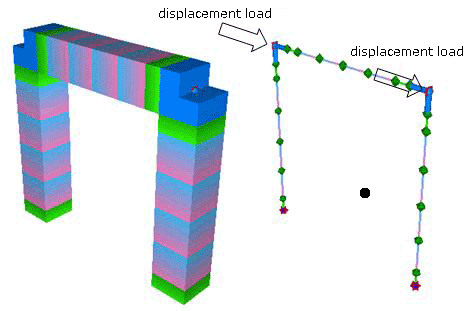 |
Following is the load displacement curve (P-ホエ curve) between fiber element and M-マ・element.
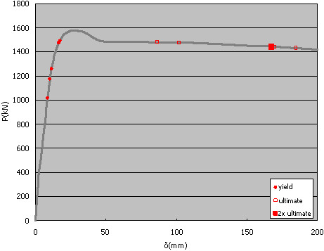 |
| The result in case of fiber element |
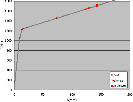 |
| The result in case of M-マ・element |
Regarding fiber elements, all of plastic hinges reach to the ultimate earlier than the curvature of one element will be two times of ultimate curvature. This determines the ultimate capacity. However, regarding M-マ・elements, all of plastic hinges reach to the ultimate curvature earlier than the curvature of one element s will do. This determines ultimate capacity.
Though significant difference cannot be seen until initial yield moment, it can be seen for the capacity and displacements at ultimate time. Allowable ductility factor calculated from above results causes about 1.5 times of difference.
This means that it needs careful attention for applying M-マ・elements to axial fluctuation models.
 |
So far, we have posted on linear elements property" in a series of three support topics.
 |
 |
 |
||
| BACK | INDEX | NEXT |