| SUPPORT TOPICS | Question & Answer Forum - VR |
Maintenance/Support Service Related Information |
| UC-win/Road |
| How to use Transmission of Section |
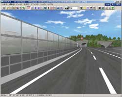
One is the use to the transparent/semitransparent soundproof wall that is used as sample data. This use is slightly complicated. The picture of section below should serve to assure you that the section turns up and down at the same position because it needs to be drawn with a single stroke from the left to the right. One side is not displayed because if both sides are displayed, transmission occurs at the both side and it will be bad-looking. Set the transmissivity 0% on the lower right of section input screen, then the section turns to completely transparent and vanish. Set the transmissivity of another section from 50% to 80%, and then it will be semitransparent. The outside is black transmission in order to display only frame. Therefore, it is possible to represent the transparent/semitransparent soundproof wall.
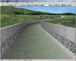
Another one is the use for river. Look the image below. Create the horizontal part assumed the surface of the water in the upper part of the bottom of the river and set it transmission. This allows representing the texture of water at the part of river. It has been possible to represent the river realistically by using the function of wetlands together. However, the function of wetland decrease performance and when apply it to river and the vertical gradient is hard, it is absolutely necessary to stagger and lab plural wetlands. Although it doesn't have the function to reflect neighboring scenes, using section transmission function allows representing more realistic river than before.
 |
 |
|
 |
 |
Page Top

| SUPPORT TOPICS | Question & Answer Forum - Dynamic Analysis |
Maintenance/Support Service Related Information |
| UC-win/FRAME(3D |
| What is Rayleigh Damping according to the element? |
First, Rayleigh damping matrix is defined by following expression.
[C] = α[M] + β[K]
| Then, | [C] : Viscous damping matrix of whole model [M] : Mass matrix of whole model [K] : Stiffness matrix of whole model |
α : Coefficient capitalizing on mass matrix β : Coefficient capitalizing on stiffness matrix |
On the other hand, Rayleigh damping according to the element can give α and β according to the element.
Here is comparison of both using simple example.
 Sine wave until 10 seconds, free vibration after that. |
 |
|||
| ▲Figure 1. Model figure | Spring which break when over stiction |
Analysis object is column. Sine wave doing resonance is given to it for 10 seconds, and then free vibration is given for 10 seconds. Spring element, which can consider break, locates on the top of column on the assumption of sliding bearing. Change the default gradient of spring, and check the effect. β multiplied [K] is 0 in Rayleigh damping according to the element.
Following left picture shows the result (of displacement history of column levee crown) of Rayleigh damping, and right one shows that of Rayleigh damping according to the element.
 |
 |
| ▲Figure 2. Right: Rayleigh Damping, Left: Rayleigh Damping according to the element | |
Rayleigh damping according to the element shows same displacement history regardless of the default gradient, but Rayleigh damping results in the response value is hold down on the whole as for high gradient K=1E+05. This shows stiffness [K] becomes bigger, and [C] becomes bigger as a result.
 |
Rayleigh Damping according to the element, that was added to Ver.3, can set damping parameter according to the element. More advanced analysis will be possible by utilizing functions. Please make use of them.
 |
 |
 |
||
| BACK | INDEX | NEXT |