
UC-win/WCOMD solver and Engineer's Studio® pre-post are integrated.
WCOMD Studio
Initial Release:2016.04.11
- USD12,000
Program Overview
FORUM8 has produced analytical program WCOMD -- developed by the Concrete Materials & Structures Laboratory at the University of Tokyo -- for 2D non-linear dynamic analysis/static analysis of reinforced concrete. WCOMD uses high-precision constitutive properties based on the results achieved through numerous experiments and theoretical verifications on concrete. These properties are highly regarded internationally, as well as in Japan, and provide accurate 2D non-linear dynamic/static analysis of various reinforced concrete structures with cracks.
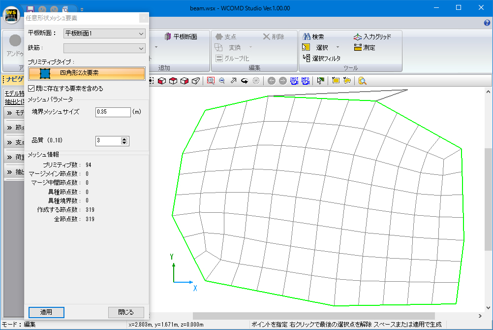
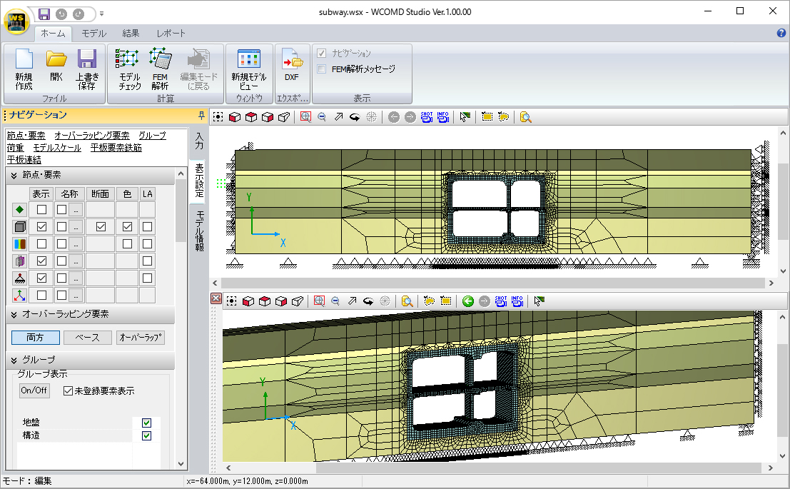
WCOMD Studio is the successor product of UC-win/WCOMD. Calculation unit is the same as that of UC-win/WCOMD, but the pre-post process has been renovated. By pre process, it is possible to mesh and divide automatically inside of the complex outline shape, and to modify data on a entering screen in tabular format. Useful input functions are available such as unlimited undo function and dockable interface which can be inserted and removed freely.
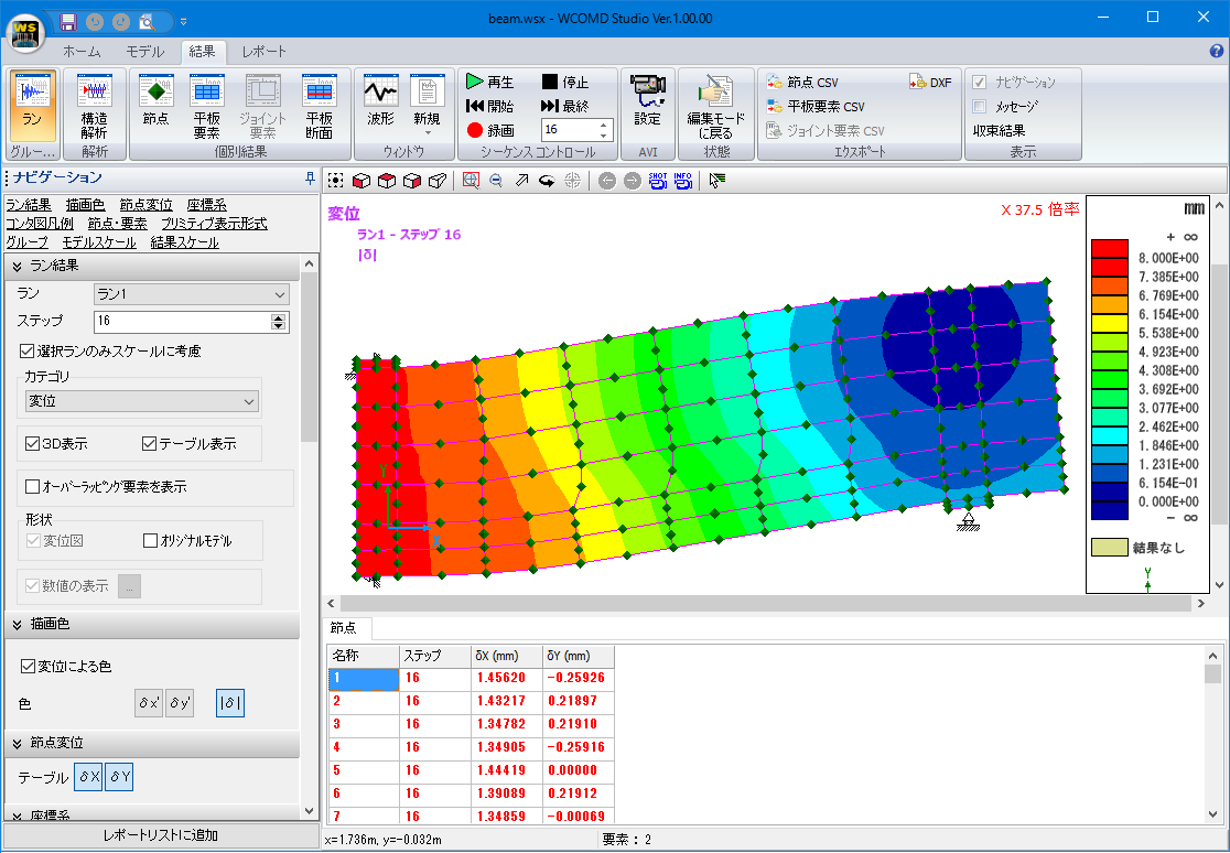
By post process, visualization is possible by figures of displacement, displacement, contour, stress contour, and cracking, and animation of displacement figure and cracking figure. Functions to output result data in text file format (CSV file) and to output reports are fulfilling.
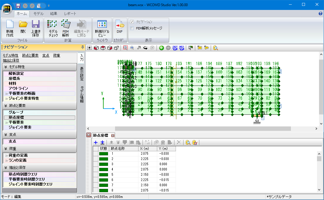
▲Input with name of node or element displayed
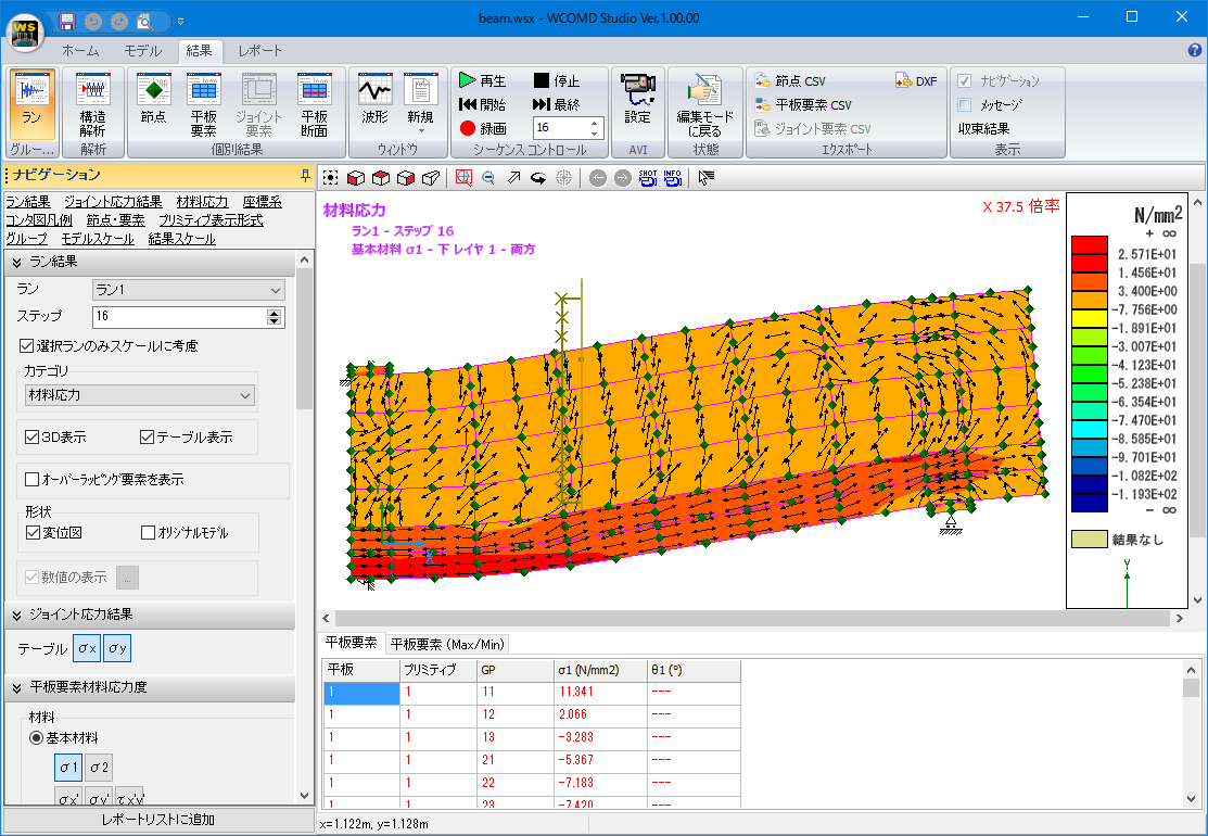
▲Direction of main stress contour and main stress
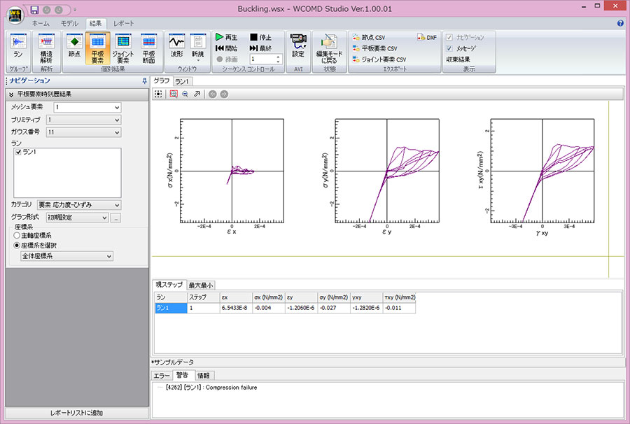
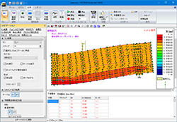
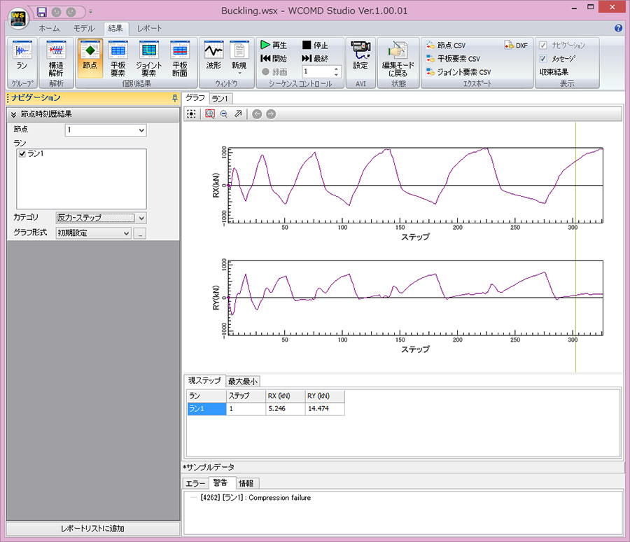
▲Plate element time history results
Related Information
- ◆New Product Introduction
- WCOMD Studio Ver.1.1 (Up&Coming '17 New Year issue)
Functions and Features
Pre process / Post process
-
By pre process, it is possible to mesh and divide automatically inside of the complex outline shape, and to modify data on a entering screen in tabular format. Useful input functions are available such as unlimited undo function and dockable interface which can be inserted and removed freely.
By post process, visualization is possible by figures of displacement, displacement, contour, stress contour, and cracking, and animation of displacement figure and cracking figure. Functions to output result data in text file format (CSV file) and to output reports are fulfilling.
▲A displacement figure and a displacement contour figure
Analysis Objects
-
Non-linear static/dynamic analysis is the main object. Dynamic analysis that considers non-linear in ground and one in RC structure. Structures with the elements specified below can be analyzed, as can all RC structures including ground models.
- RC Plate RC elements:
RC Plate is defined by concrete type, reinforcing steel, and steel ratio, and handled as a distributed cracked model. Plain concrete is considered an RC element with a steel ratio of zero.
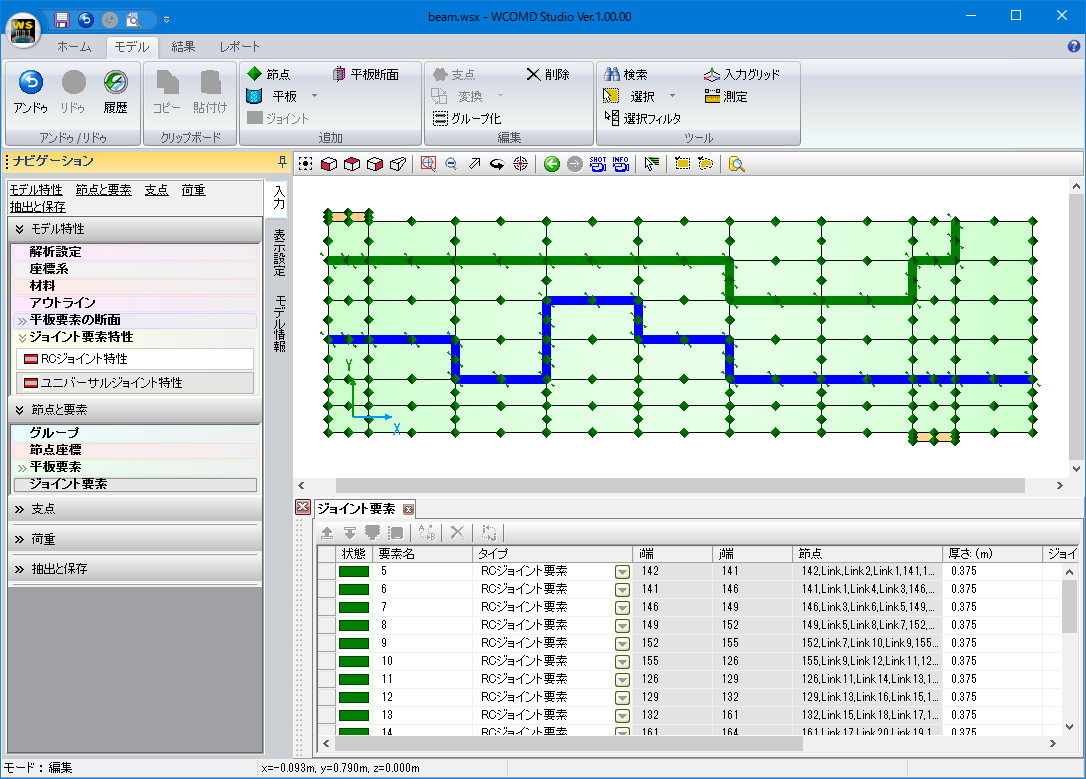
- RC Joint (RC joint element):
RC Joint is an element applied where the section radically changes (quake-resisting walls, frames, pierstud, footing, etc.) and defined by steel ratio, steel diameter, steel anchor length, and so forth.
- Soil (Ground element):
Soil is an element that defines ground by transverse elastic wave speed, transverse rigidity, transverse strength, and so on
- →Constitutive laws of the ground - Ohsaki model
→Application to underground structures- Universal Joint (Boundary element):
Universal Joint is an element applied at a boundary of different elements (ground and footing, for example) and is defined by transverse rigidity, contact rigidity, and so forth.
- Elastic Plate (Elastic element):
Elastic Plate is an element representing linear behavior. Applying this element in RC areas where no cracking occurs can reduce redundant calculations.
Also, an Overlapping element is supplied to represent unevenness of bar arrangement in RC section (the center area has less reinforcement than other areas), piles and ground, and boundary conditions on either end of the ground.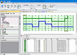
▲Arrangement of RC joint and universal joint
Analysis Contents (subject load)
-
The following analyses are supported.
- 1. Non-linear dynamic analysis
Performs non-linear time history response analysis. Vertical acceleration as well as horizontal acceleration can be simultaneously applied as seismic acceleration.
- 2. Static analysis
Analyzes weight and conditions where incrementally forced displacement and incremental load are given. The loading patterns of incremental forced displacement and incremental load are:
(1) Simple: Simple increment up to defined step
(2) Cyclic: Simple increment up to defined step, and then simple decrease to the starting point.
(3) Reversal Cyclic: Cyclic + Reversal Cyclic
(4) Increasing Cyclic: Cyclic + 2*Cyclic + 3*Cyclic + … and so on
(5) Reversal Increasing Cyclic: Rev.Cyclic + 2* Rev.Cyclic + 3* Rev.Cyclic + … and so on
Including the above patterns, there are ten patterns including the case where load is applied with certain shocks in the patterns above (the time interval can be set from 0.01 seconds to 1000 seconds). Any loading conditions can be analyzed through appropriate use of these patterns.
These analyses can be performed simultaneously and are performed in the order "weight", "static load", and then "dynamic load". Dynamic analysis can therefore be performed by entering seismic waves and applying vertical earth pressures and horizontal earth pressures as the initial condition remains unchanged.
Analysis Results
-
Damage is evaluated based on defined damage criteria. At each calculation step for all elements and all nodes, the following are required:
- Cracking condition (orthogonal and parallel cracks in the cracking direction)
- Average stress result (stress result of X and Y directions, main stress result, deviation stress result, direction of main stress result)
- Yield results, response displacement, response speed, response acceleration, reaction force, section force
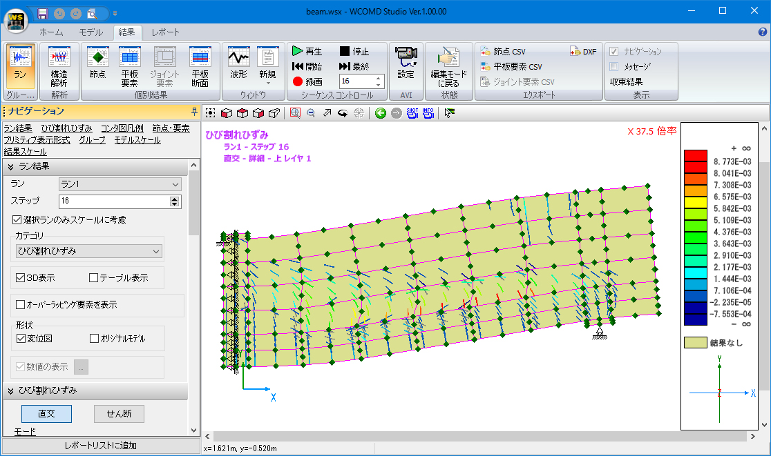
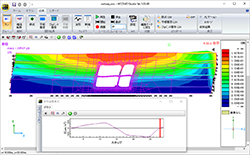
All of these can be evaluated on the screen and utilized when creating reports. Damage level can also be evaluated based on the size of distortions. Occurrences of cracking, displacement conditions, stress conditions, and so on can be viewed as an animated representation at each step. Loading conditions are shown in static analysis results, and input waveforms are displayed in dynamic analysis, allowing accurate understanding of response status. Animation speed and displacement level are among the options.
▲Conditions of displacement and cracking
Features of mesh creating function
-
Plate elements can be created by mouse operation. Three kinds of commands are available.
- 1. Free-form mesh element
Polygon can be made by left-click in the model space several times. Right-click to undo.
- 2. Square mesh element
Click 2 points in the model space to create a rectangle whose diagonal is the line connecting the clicked points.
- 3. Shape of outline
Plate elements can be created by combining outline(shape) and coordinate system(for positioning). They will be located in the model space so that the origin of the outline will match the origin of the coordinate system. If the name of outline and the name of coordinate system are the same, they will be automatically recognized and plate elements will be located continuously.
▲Free-form mesh
About performance verification
-
Performance verification of structures is supported by high precision and detailed condition setting.
Residual volume of strain and deformation are analyzed and calculated by setting the loading pattern and the range of strong seismic wave.
Price
Product Price
-
■Product Price
Product Price WCOMD Studio USD12,000 ■Price of Floating License
Paying 40% of the product price allows anyone to use the product on any PC anywhere in the world.
Product Price WCOMD Studio USD4,800
Special Price
Special Price
-
Product Object Product Price Note WCOMD Studio UC-win/WCOMD Ver.2 USD3,400 Special price for maintenance contract user Price of Subscription Service Contract
Price of Subscription Service Contract
-
■Support information
-Software upgrade -Technical inquiry (Email, Tel)
-Download service -Maintenance and update notifications via email
* We are sequentially making a transition from the maintenance-support service to [Subscription Service] from April 1, 2016 in order to enhance support for diverse product usage and to reduce license management cost.
Product Subscription cost
of first yearSubscription cost
of subsequent years
(annual cost)Subscription (WCOMD Studio) Free USD4,800 Subscription (WCOMD Studio Floating) USD6,720
Price of Rental License / Floating License
■Rental license : Short term licenses available at a low price
■Rental floating license : After web activation, anyone can use the products on any PC anywhere in the world.
■Rental access : You can increase the number of licenses you own and use these additional licenses for a specific period of time (1 month to 3 month) at your discretion. We will later send you an invoice based on your usage log. The advance application is 15% off of the regular rental license price. Please place an order from User information page.
*Rental / Floating Licenses were introduced on September 2007 to enhance user experience and convenience of our products.
*Duration of Rental / Floating Licenses cannot be changed after starting these services. Re-application is required to extend the rental and floating license duration.
Rental license / Rental floating license
-
■Rental License
Product 2 month 3 month 6 month WCOMD Studio USD5,400 USD6,360 USD7,800 ■Rental Floating License
Product 2 month 3 month 6 month WCOMD Studio USD9,000 USD10,680 USD13,200 Academic Price
An Academic License can be provided for educational purposes and used by teachers, lecturers, academic researchers, and students.
Academic Price
-
Product Academic Price WCOMD Studio USD9,600 Version Update History
Version Update History
-
The version upgrade and revision upgrade (without charge) contents are listed as following.
WCOMD Studio Version Release date Update contents 1.0.0 18/06/12 - 1. Windows standard ribbon (GUI)
- 2. Backup of input data file
- 3. JMA seismic wave data can be imported
1.1.2 17/06/26 - 1. Displaying the normal vector of the cut plane in the coordinate system of plane section forces.
- 2. Added the ability to show/hide the overall coordinate system on the model screen and
the description on the results screen.
1.1.1 17/02/07 - 1. Improved copy function in "Model | Edit | Copy/Move" ribbon
1.1.0 17/01/16 - 1. The strain based design concepts as specified in the Japan Standard Specifications for
Concrete Structures 2012, Design. This involves calculating and checking the deviatoric strain
and normalised cumulative strain energy and using these as damage indicators. - 2. It is now possible to start multiple instances of the application and run calculations simultaneously.
- 3. Input of the unreinforced concrete C setting in the RC plate section editor has been improved.
- 4. An extension was made to the failure criteria result reporting.
- 5. Some improvements were made to the view control commands that controls model rotate or movement.
- 6. A function (button) was added for the input table editors that automatically adjusts the width of a column.
- 7. The operation to show/hide groups has been improved.
1.0.2 16/07/11 - 1. A function to select nodes or elements in group has been added.
- 2. The order sorting of primitive has been enhanced.
- 3. CSV export has been improved.
1.0.1 16/05/23 - 1. Addition of a command to mirror selected elements and nodes and to move them to their mirror's position.
- 2. Addition of a command to change the size of arrows or the threshold value considered as the same coordinates.
1.00.00 16/04/11 - New Release
Product Operation Environment
Product Operation Environment
-
OS Windows 10 / 11
*Work in both of 32bit OS and 64bit OS
It works by OS provided 32bit emulation technology in 64bit OS.CPU (Required) Greater than intel Core 2 Duo 2.0GHz or the one having the same performance
(Recommended) Highest possible performance CPU (Ex. Core i7 series)Required Memory (including OS) Greater than 4GB RAM is recommended (varies according to analysis models and analysis steps). Required Disk Capacity Greater than 350 MB for installation, few MB to tens of GB for calculation
(varies according to analysis models and analysis steps)Display (Image Resolution) More than 1280 x 800, color number 32bit
Please use a default setting for a property of a screen and normal size (96) for a DPI setting.File Export CSV, DXF/DWG
Order / Contact Us
Order / Contact Us
-
■ Inquiry
Contact us from Sales inquiry or email to ist@forum8.co.jp or forum8@forum8.co.jp
Samples
▲Input with name of node or element displayed
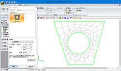
▲A function to mesh and divide automatically
inside of the complex outline shape
▲Arrangement of RC joint and universal joint
▲Displacement figure and displacement contour figure
▲Direction of main stress contour and main stress
▲Condition of displacement and cracking
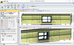
▲ Integrated analysis of the ground and the structure
▲ Integrated analysis of the ground and the structure
▲ Free form mesh
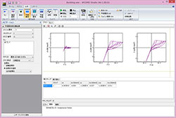
▲ Plate element time history result
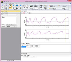
▲ Node time history result
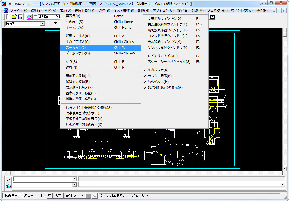
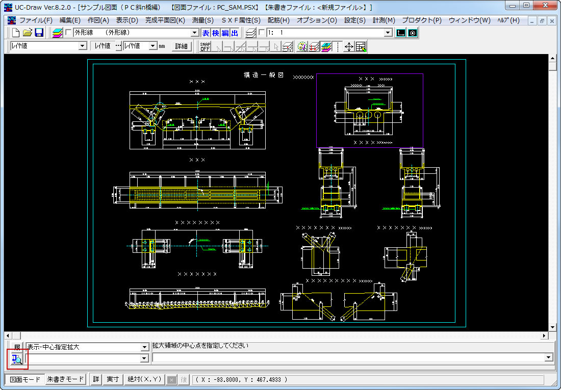
1.表示関連
- 作図途中で拡大・縮小表示は可能か。
-
以下の方法で行えます。
- スクロールマウスのセンターホイルを回す。
- 「表示移動ウィンドウ」で、編集中の画面内で表示したいエリアを指定する。
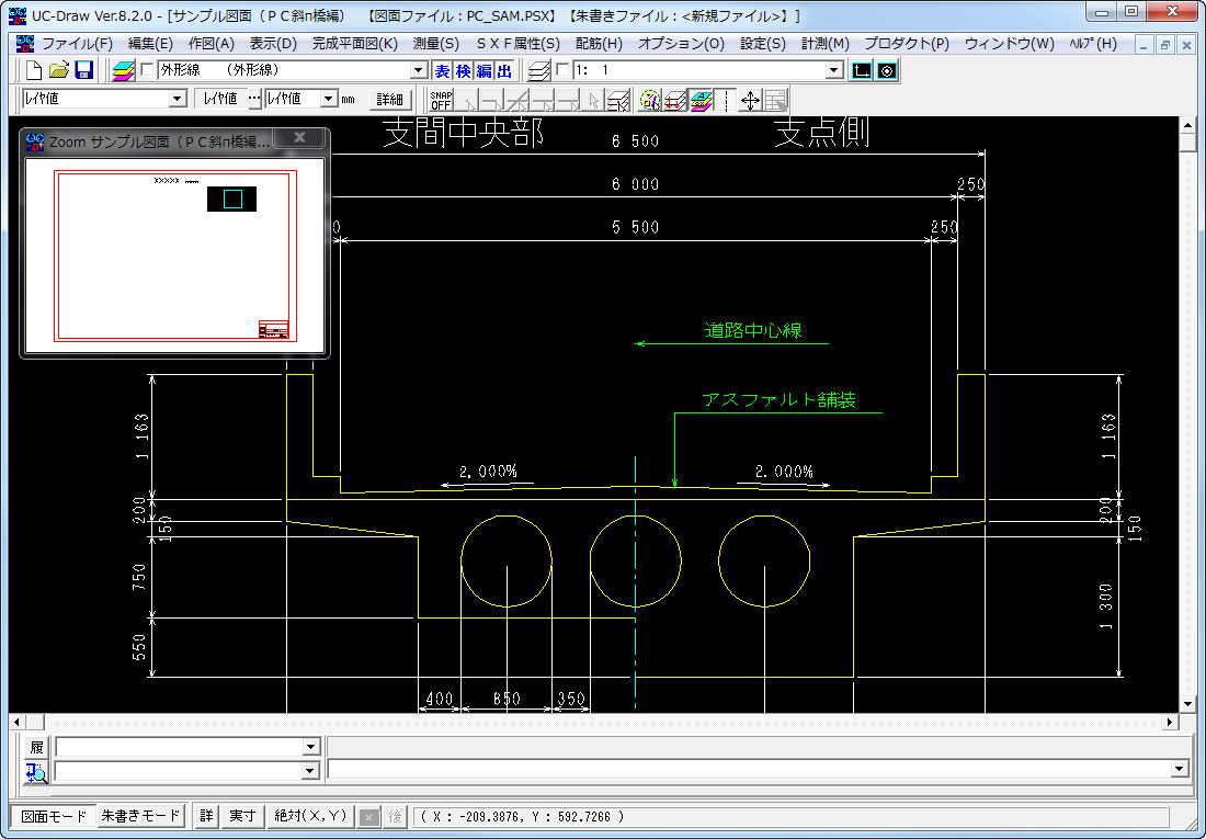
- 表示機能(ズームイン、ズームアウト)を使用する。
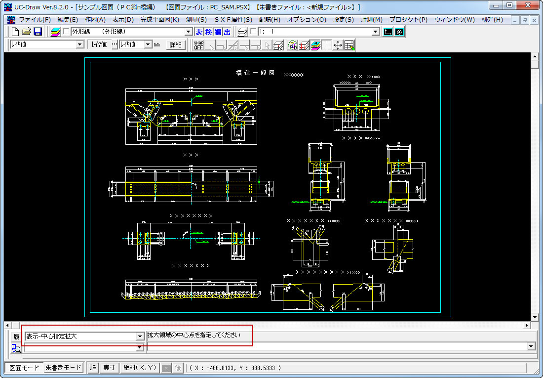
- 「作図編集入力バー」の「割り込み部分拡大」ボタンを使用する。

2.設定関連
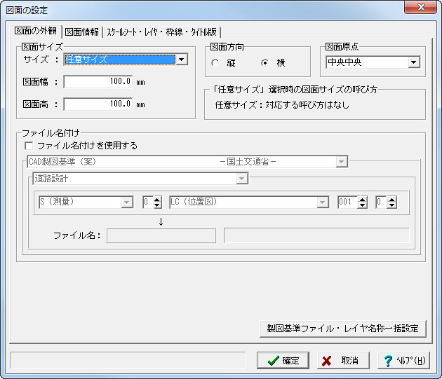
- 作図可能な図面サイズは?
-
A1~A4やB1~B5等の規格サイズ・ANSIサイズ・建築用サイズに加えて、任意で自由に図面サイズを指定できます。 新規作成や図面追加時の設定で、また設定後もサイズ変更が可能です。
3.ファイルIO関連機能
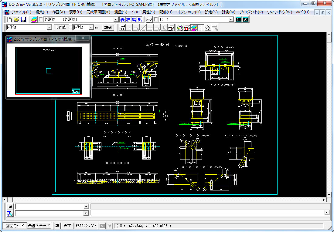
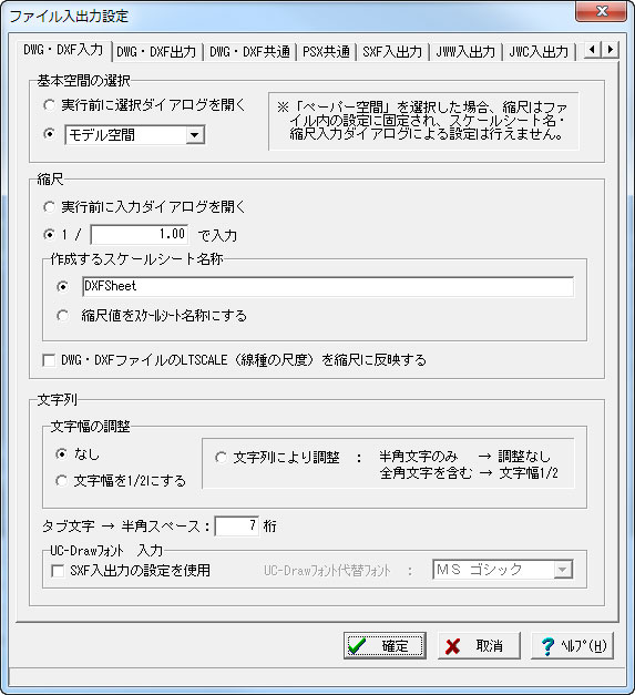
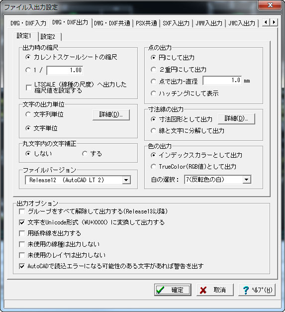
- AutoCADの図面データ(DWG・DXF)ファイルの入出力は可能か。
-
可能です(DWG・DXF:R12~AutoCad 2007形式)。UC-Drawは複数の図面を同時に扱えるため、DWG・DXFファイル出力の際は、図面毎に複数のDWG・DXFファイルに保存します。
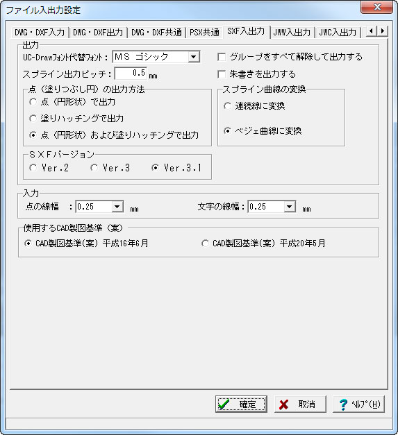
- CADデータ交換標準フォーマットである SXF形式(P21・SFC)ファイルの入出力は可能か。
-
可能です。SXF形式(P21・SFC:SXF Ver.2.0~SXF Ver.3.0)に対応しています。
4.オプション関連
- UC-1設計シリーズ製品で生成した配筋図や加工図・鉄筋表の編集は可能か。
-
UC-1設計シリーズ製品で保存した図面ファイル(PSX)をUC-Drawで読込み・編集を行うことが可能です。UC-1設計シリーズ製品で保存した図面ファイル(PSX)では、加工図・鉄筋表の関連を保持していますので、加工図を編集した際に鉄筋表にもその修正を反映することが可能です。
>> サポートページ UC-Draw Q&A集


LOADING