Fiber Division of Beam/Column
Plastic Hinge
Treatment of Corner and Connection of Beam and Column
Built-in Constructions
Loading Conditions
Load Definition
Anti-seismic Investigation
Residual Displacements
Attentions on Analysis
Static Forcing Position Treatment
Cell Division of Fiber Section
The cell division in a fiber section has two aims. One is to reflect material distribution of concrete and steel. The other is to precisely cast non-linear state of locality in the beams or columns. Therefore, the fine division will result in a good simulation of structure and a high sensitive response. But meanwhile the fine division will result in a long computation time and a huge file space. The faithful reflection of analysis results to the model under minimum cell number is the pursued rule for the cell division.
The general rule is suggested below for the non-plastic section and plastic section. But they should be treated more flexibly based on a specific condition like the load strength, section dimension and material composition.
- Non Plastic Section
The parts of beam or column that did not enter crack nonlinear state during load action is called non plastic part and the defined fiber section here is called non plastic section. For crack nonlinear does not appear, the section can roughly be divided. Based on the testing experiences, it has better to divide it in 7x7 cells as the following figure. - Plastic Section
The crack area in beams or columns can be modelized as fiber element with plastic section. Due to the complex behavior in the plastic field, the fine cell division is expected to use to simulate the nonlinear progress in the plastic area. The division of 15x15 cells is suggested on the basis of our past testing results as figure below. - Eccentrically Forced Section and Unsymmetrical
Section
The section with an eccentric force or unsymmetrical geometrical shape must be divided with considering their possible crack nonlinear fields. The cell section can be first roughly divided, and try to analysis. Then for the plastic area, the fiber section is further finely divided.
Fiber Division of Beam / Column
The nonlinear response simulation of RC structures
is the power point of COM3 calculations.
The nonlinear parts have to be divided and
meshed finely to present the complex nonlinear
performance of RC materials. However if too
fine elements are divided, the consuming
time will increase sharply while the result
precision is kept unchanged. This is not
hoped.
The general dividing number in the possible plastic hinge parts based on our test is suggested to use two fiber elements and their length is the half of cross section effective height. The following figure shows the dividing number and their corresponding displacement results.
Two fiber elements using for plastic hinge parts are just for general recommendation. For a specific column or beam, the fiber element number can adjusted according to the section shape, reinforcement ratio and load strength.
2. Division of Non-plastic Parts
The parts of RC components that do
not enter
plastic field suffer some simple strain-stress
variety. The fiber element can be taken
longer
and the analysis time can be saved
too. But
over rough division of beam or column
will
result in an error in non-axial elastic
bending
deformation. Therefore here the plastic
hinge
length is suggested to use. Like plastic
hinge parts, this length is affected
by the
section shape, reinforcement ratio
and load
strength. For a real model, a appropriate
adjustment is needed.
Plastic Hinge
1. Location of Plastic Hinge
For a pier bridge, the hinge part will
appear
at the base part of pier column
For Rahman structure bridges, the hinge parts will appear at the upper and lower parts of column.
For beams, the hinge parts will appear at the two side.
For Rahman structure bridges, the hinge parts will appear at the upper and lower parts of column.
For beams, the hinge parts will appear at the two side.
2. Length of Plastic Hinge
By the Road and Bridge CODE of Japan
Road
Association, the plastic length is only for
in which,
The plastic length in the Railway Structural
Design Standard is expressed as
Due to the difference between the real structure and analysis model, the hinge location and length are some different from above definition. It is suggested that the static preliminary analysis be conducted before a formal analysis.
in which,
| D | : Scale of section( diameter for circle section, the scale length in the acting direction for the rectangular section) | |
| h | : Height from foot base side of bridge to the inertia acting position on upper structure. |
Due to the difference between the real structure and analysis model, the hinge location and length are some different from above definition. It is suggested that the static preliminary analysis be conducted before a formal analysis.
Treatment of Corner and Connection of Beam and Column
1) Using Non Failure Section
In general, the plastic response will not
appear in the cross part between beams and
columns as figure below. Therefore it should
use non failure section check in the Section
Material Editor window for these parts. The
non failure section fiber element will behavior
with an elastic constitutive law and the
plastic non-linearity will not happen. The
section can take as simple as possible.
2) Using Zero Weight
For avoiding the redefinition of weight
in
the corner parts, it should define
a part
of fiber elements in the cross field
to have
a zero weight. The zero weight can
be defined
by inputting zero unit weight in Cell
Material
tab of Section Material Editor windows
under
the following window.
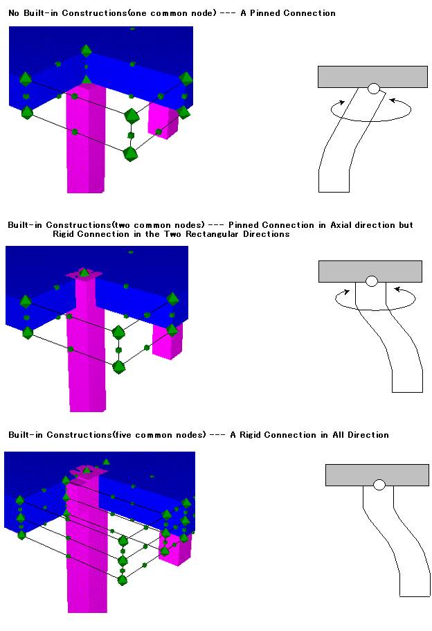
Built-in Constructions
Loading Conditions
For Static Analysis, there are Displacement-controlled
analysis and Load-controlled analysis.
For
the model with fewer statically unbalanced
dimensions, the stability of Load-controlled
analysis would be worse. In that case,
the
alterations are effective to reset
the increased
unit-load less or change to the Displacement-controlled
analysis.
2. Dynamic Analysis
At the case that the observed earthquake
waves are applied as the input wave
loads,
it is recommended that the main part
of them
(several seconds) are taken out for
the analysis.
When the input wave loads are composed
of
the combination of SIN waves, it may
be better
to make a few large waves continuously
than
multiple small waves continuously.
It is also effective to define the input wave period closer to the natural period of the structures. To make the execution time shorter, it is more effective to reduce the total analysis steps than reset the input waves to only one direction from three directions simultaneously. In order to calculate up to the last step with keeping the good accuracy of the convergent analysis, it is efficiently to set the time interval of the input wave by 0.02 second at first and reset it smaller by 0.01 second and 0.005 second in order at the case when the solution might be diverged.
It is also effective to define the input wave period closer to the natural period of the structures. To make the execution time shorter, it is more effective to reduce the total analysis steps than reset the input waves to only one direction from three directions simultaneously. In order to calculate up to the last step with keeping the good accuracy of the convergent analysis, it is efficiently to set the time interval of the input wave by 0.02 second at first and reset it smaller by 0.01 second and 0.005 second in order at the case when the solution might be diverged.
Load Definition
In the load type definition, three
kinds
of load, Dead Weight, Static and Dynamic,
are included.
To the load type combination, each three kinds of load can be calculated independently. And also the combination of loads is possible, Dead Weight + Static, Dead Weight + Dynamic, Dead Weight + Static + Dynamic and Static + Dynamic. The result of the former loading analysis is transmitted to the next loading analysis. In this case, analysis order is set by Dead Weight, Static and finally Dynamic. So, it is not allowed to load Static after Dynamic
To the load type combination, each three kinds of load can be calculated independently. And also the combination of loads is possible, Dead Weight + Static, Dead Weight + Dynamic, Dead Weight + Static + Dynamic and Static + Dynamic. The result of the former loading analysis is transmitted to the next loading analysis. In this case, analysis order is set by Dead Weight, Static and finally Dynamic. So, it is not allowed to load Static after Dynamic
2. Dead Weight Analysis
Dead Weight Analysis is performed with loading
the gravity weight to Vertical direction
(Y-direction).
3. Static Analysis
For Static Analysis, many loading patterns
are registered in the program. By composing
these loading patterns, you can define your
own loading pattern. Displacement control
and Load control are available.
[Note for Displacement control analysis]
For the analysis by Displacement controlled loading, it is necessary to restrict the boundary condition in the loading direction at the loading node. For example, the vertical direction of the loading node would be restricted when Beam element is loaded in vertical direction by displacement control. In this case, the result of the displacement only by the self-weight of the structure cannot be obtained because of the restriction in vertical direction. In the same way, the horizontal direction of the loading node would be restricted when Column element is loaded in horizontal direction by displacement control. At this time, the correct results cannot be obtained even if Dynamic analysis is executed after Static analysis because of the restriction in horizontal
4.Earthquake Dynamic Analysis
Dynamic analysis is executed with defined
acceleration waves.
The acceleration waves are loaded at the restricted node in all six degrees. Then, the loaded nodes should be restricted in all six degrees even at the case of the loading in only X-direction.
The correct results cannot be obtained even if Dynamic analysis is executed after Static analysis by Displacement controlled loading. When the dynamic analysis has to be executed after Static loading, Static loading by Load control should be carried out.
The input dynamic waves can be generated by tool menu of program or use a real time-history record. The waves generated by tool menu can be used to test structure dynamic properties.
The real time-history record is used to check the safety of structure. For a specific record, many information is included such as earthquake strength, seismic fault, seismic wave propagating routine and the local field properties. When the record is selected, the location and surround geological characteristics of project have been taken into account. Its frequency content and peak value will influence the response of structures. The simulated record form a characteristic response spectrum can also be used for anti-seismic investigation too.
The input direction of record must be justified for a most dangerous input. For a bridge, the bridge axial direction and its normal direction is considered for the Due to the stochastic characteristics of earthquake records, more than one record with the same magnitude and prominent frequency are suggest to be used to calculate. The average results can be taken into the project check.
Anti-seismic Investigation
The three items on safety should be
investigated
for the structures under/after the
earthquake
action.
1) Bending Capacity Check and Shear Capacity Check
The failure mode is firstly judged and then the acting bending moment or acting shear force is compared with sectional bending moment capacity or shear force capacity. For example, a judgment procedure is given as below.
1) Bending Capacity Check and Shear Capacity Check
The failure mode is firstly judged and then the acting bending moment or acting shear force is compared with sectional bending moment capacity or shear force capacity. For example, a judgment procedure is given as below.
- Failure Mode Judgment
(V·a)/Mu > 1.0 Bending Failure Mode
(V·a)/Mu < 1.0 Shear Failure Mode
(V: shear force capacity, a: shear span length, Mu: bending moment capacity) - Bending Failure Mode
M/Mu<1.0
(M: acting bending moment) - Shear Failure Mode
S/V<1.0
(S: acting shear force)
2) Damage judgment
The definition of damage criteria of structures depends on artificial settings for the calculating value. Not only the project cost and importance but also the respair/retrofitting cost affected the criteria level. The strain of steel and concrete is used in the COM3(Fiber) to define the model damage criteria.
The definition of damage criteria of structures depends on artificial settings for the calculating value. Not only the project cost and importance but also the respair/retrofitting cost affected the criteria level. The strain of steel and concrete is used in the COM3(Fiber) to define the model damage criteria.
3) Residual displacements
The Residual displacement must to be checked for a load action, especially for the earthquake action. The safe residual displacement is needed to keep under certain level. The Road and Bridge Code of Japan Road Association , for example, set a following criteria for the B type bridge( an important type).

in which,
 : Residual Displacement
 : Permitted residual displacement, the 1/100
height from the down side of pier to
the
acting position of inertia forces.
: Permitted residual displacement, the 1/100
height from the down side of pier to
the
acting position of inertia forces.
The Residual displacement must to be checked for a load action, especially for the earthquake action. The safe residual displacement is needed to keep under certain level. The Road and Bridge Code of Japan Road Association , for example, set a following criteria for the B type bridge( an important type).
in which,
2. Investigation Points
The anti-seismic investigation must be conducted
for the more than one wave. The spectrum
of input waves must have the frequency characteristics
of local fields. The Road and Bridge Code
of Japan Road Association suggests 3 waves
at least to input, The average result of
calculation is used to final judgment.
Residual Displacement
For static load calculations, the unload action has to be appended to the last period of load action so that the condition for measuring residual displacement is kept a unforced state. Unload process can be realized by the cycle load or the opposite load.
For dynamic load calculations, besides the input waves have to back to zero, the zero input has to be kept for a period of time for obtaining a still position because of the natural vibration of structure itself. Length of time for zero inputting depend on the damping of structures. For a high damping structure, the lasting time of free vibration until still will be short. For a low damping structure, it will be long. The stiffness of structures also affects the lasting time.
A more simplified and approximate method is to let free vibration to last two or three cycles. And the average position of structural displacement vibration is taken as a still position for the residual displacement computation.
Attentions on Analysis
It should be taken care that the calculated
results (section forces, strain and stress)
be not saved if the boxes in the fiber section
definition are not checked. By default these
boxes are not checked. But the parts like
the base plastic hinge parts of columns have
to be checked. Therefore the responses of
the nodes such as accelerations, displacements
and reactions are saved regardless of these
checks.
These check boxes are set for reducing the result file size. If all the gauss point sections and cells are checked, the size of the result files will reach hundreds of MB. In addition, the time for reading them will last much long.
These check boxes are set for reducing the result file size. If all the gauss point sections and cells are checked, the size of the result files will reach hundreds of MB. In addition, the time for reading them will last much long.
2. On the analyzing time
The analyzing time firstly depends
on the
size of the model and nonlinear performance
of materials in the analysis will increase
the time. It is suggested that other
applications
be stopped when the calculation is
being
conducted. The size of samples and
their
analyzing time can give you some implication
on this respect as below.
TABLE The Relationship of Model File Size and Calculation Time
( Computer : Pentium III 800MHz, Memory 256 MB )
TABLE The Relationship of Model File Size and Calculation Time
( Computer : Pentium III 800MHz, Memory 256 MB )
| a | Calculation Time | Step Number | Node Number | File Size |
| Sample1 | About 2 Min. | Static 315 | 11 | 7MB |
| Sample2 | About 7Min. | Static 425 | 19 | 14MB |
| Sample3 | About 20 Min. | Dynamic 250 | 85 | 40MB |
| Sample4 | About 2.5 Min. | Dynamic 250 | 264 | 86MB |
3. On the analyzing conditions
The values of Maximum iteration and
Convergence
order in the Analysis Model Setting
are suggested
to use the default values. The default
values
are
If the default values cannot assure
the successful
calculation, one or both of two values
can
be modified to make the calculation
re-execute
until a successful calculation is finished.
But this may result in a longer computing
time.
| Maximum iteration.....12 | |
| Convergence order.....1% |
4. On the Iso-solid elements
The node number of iso-solid elements can
be taken as 20 or 8 in general. But in our
program the 8 node element is employed by
considering computer property. But it should
be noted that the middle nodes at the edge
of solid cube are set for editing models.
In fact these nodes are not used for calculation
and therefore they cannot be defined for
boundary conditions and the loads.
The Iso-solid elements are suggested to use in the model that the Fiber elements are difficult to model the component of structures like the top floor plates of Sample 4. However it should be paid attention for defining the intersecting parts between the Iso-solid element and fiber elements. An example is shown in the following figure. The spinning of iso-solid components around the bridge pier axis will become free. If these parts are modeled by the Fiber elements, the fiber section can be defined as 'Non failure'.
Notice:
The strength of Iso-solid elements should be set large enough to keep them response in the elastic range and not reach the fracture. The setting of the strength input box is for the future vision.
Static Forcing Position Treatment
However, the beam and the column overlap at the connecting parts. The weight of column parts has to set to zero.
| UC-win/COM3(Fiber) |